Page 63 - RM_2022
P. 63

03                              High pressure equipment


                                               Suttner regulation valves
       ST-291
       ST -291                              ST-291 with switch                  Repair kits ST-291


                                        192                                 192

                                                                                                 Switch (IP67) with cable
                                                                                                 1,200 mm
                                     57                                  57
                                                                               Piston rod         R+M Nr.
                                                                                                  200 291 450
                                                                                R+M Nr.
                                                                                200 291 495
                               97,5                                97,5

         = inlet 3/8" F.    = outlet 3/8" F.    = bypass    = inlet 3/8" F.    = outlet 3/8" F.    = bypass
       1/2" F. Max. 350 bar / 90 °C        1/2" F. Regulation valve with pressure switch (IP67)
                                           and cable 1,200 mm. Max. 350 bar / 90 °C  Check valve  Seal kit
       R+M Nr.                              R+M Nr.                             R+M Nr.           R+M Nr.
       200 291 500                40 l/min  200 291 550               40 l/min  200 291 490       200 291 485
       ST-280
       ST -280                                                Repair kits ST-280
                                              = inlet 3/8" F.
                                              = outlet 3/8" F.
                                              = bypass 1/4" F.
                                        185    = pressure gauge
                                           1/4" F.
                                           Max. 250 bar / 80 °C

                                    43


                                75
                                                             Type A            Type C             Type D
       R+M Nr.                                                R+M Nr.           R+M Nr.           R+M Nr.
       200 280 510                  30 l/min                  200 280 650       200 280 646       200 280 526


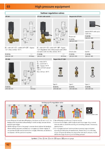
                                                Setting up of a regulation valve
           1          A      2                 3                 4                5
                      B                 B                                                    A
                                                         B
                      C                                  C
                                                                                                   www.rm-suttner.com


        1.  Loose fixing nut (A) and take off handgrip. Also loose nut (B) and nut (C). Put   3. Take off handgrip and fix nut (C) against nut (B).
         handgrip back in position without fixing it. Switch on high pressure device   4.  Unscrew the handgrip until it bumps to nut. Press trigger of gun several
         and press gun trigger.                                times in order to control the working and switching pressure. If necessary,
        2.   While keeping an eye on the gauge`s pressure slowly tighten the handgrip.   repeat phase 2.
          When working pressure is attained turn handgrip one rotation tighter. In   5.  Turn handgrip back until minimum/steam pressure stage is obtained
          this position nut (B) must be next to the handgrip. Otherwise, nut (B) has to   ( according to indication of manufacturer). Mount fixing nut until swing
          be adjusted until this position is reached.          of grip. Fixing nut (A) defines the stage of low and steam pressure, nut (B)
                                                               defines the stage of working and switching pressure.
                                     Symbols     flow     inlet     outlet     bypass     pressure gauge


         62
   58   59   60   61   62   63   64   65   66   67   68