
Page 99 - BVA_2022
P. 99
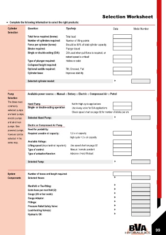
Pumps / Cylinders Operation and Speed Chart Selection Worksheet
Complete the following information to select the right products:
Cylinder Question: Tips/help Data Model Number
Selection
Total force required (tonne): Total load
Number of cylinders required: Number of lifting points
NUMBER OF STROKE PER CM OF CYLINDER PLUNGER TRAVEL Force per cylinder (tonne): Should be 80% of total cylinder capacity
Model 5 Tonne 10 Tonne 15 Tonne 25 Tonne 30 Tonne 50 Tonne 75 Tonne 95 Tonne Stroke required: Plunger travel
Number No load Load No load Load No load Load No load Load No load Load No load Load No load Load No load Load Single or double-acting (D/A): D/A used when pull force is required, or
POWER SOURCE: MANUAL retract speed is critical!
P601S 3 3 6 6 9 9 14 14 17 17 29 29 42 42 54 54 Type of plunger required: Hollow or solid
P350 2 8 5 18 7 25 11 41 13 52 22 87 32 127 41 162 Collapsed height required:
P1000 1 3 2 7 2 9 3 15 4 19 6 31 8 46 11 58 Optional saddle required: Tilt, Grooved, Flat
P1201 1 3 2 7 2 9 3 15 4 19 6 31 8 46 11 58 Cylinder base: lmproves stability
P2301/P2301M 1 3 2 7 2 9 3 15 4 19 6 31 8 45 10 58
P4301/P4301M 1 3 2 7 2 9 3 15 4 19 6 31 8 46 11 58
P8701/P8701M 0.1 1.4 0.2 3.4 0.2 4.3 0.3 7 0.4 9 0.6 15 0.8 22 1.1 28 Selected cylinder model:
SECONDS PER CM OF CYLINDER PLUNGER TRAVEL Pump Available power source: □ Manual □ Battery □ Electric □ Compressed Air □ Petrol
Model 5 Tonne 10 Tonne 15 Tonne 25 Tonne 30 Tonne 50 Tonne 75 Tonne 95 Tonne Selection
Number No load Load No load Load No load Load No load Load No load Load No load Load No load Load No load Load The three most Hand Pump Not for high cycle applications
POWER SOURCE: AIR (BASED ON 7 BAR AIR PRESSURE) commonly Single- or double-acting operation Use 4-way valve for D/A applications
PA600/PA600H 0.4 2.6 0.9 5.8 1.2 8.1 2 13.3 2.5 16.8 4.2 28.3 6.2 41.6 8 53.1 selected pumps Check speed chart on page 92 for number of stroke per cm
PA1500 0.4 2.1 0.9 4.8 1.2 6.8 2 11.1 2.5 14 4.2 23.6 6.2 34.6 8 44.2 are hand pumps,
PA1500M 0.4 2.6 0.9 5.8 1.2 8.1 2 13.3 2.5 16.8 4.2 28.3 6.2 41.6 8 53.1 electric pumps Selected Hand Pump:
PA2000 0.4 2.6 0.8 5.8 1.1 8.1 1.9 13.3 2.3 16.8 4 28.3 5.8 41.6 7.4 53.1 and air-driven
PA3801/PA3801M 0.4 2.6 0.8 5.8 1.1 8.1 1.9 13.3 2.3 16.8 4 28.3 5.8 41.6 7.4 53.1 pumps. Gas Electric or Compressed Air Pump
PA1500L/PA3801L 0.4 2.3 1 5.4 1.4 7.6 2.2 12.5 2.8 15.7 4.7 26.6 6.9 39 8.8 49.8 powered pumps, Need for portability:
PA7550/PA7550M 0.4 2.6 0.8 5.8 1.1 8.1 1.9 13.3 2.3 16.8 4 28.3 5.8 41.6 7.4 53.1 however can be Required useable oil capacity: 1,2 x oil capacity
POWER SOURCE: ELECTRIC (SPEED BASED ON 50HZ) selected in the high cycle = 2 x oil capacity
PE30S… 0.1 1.5 0.2 3.3 0.2 4.6 0.4 7.6 0.5 9.6 0.9 16.2 1.3 23.8 1.6 30.4 same way. Available Voltage:
PE40S… 0.1 0.7 0.2 1.7 0.2 2.4 0.4 3.9 0.5 4.9 0.9 8.2 1.3 12.1 1.6 15.4 Lifting speed (lmportant/not important): Use speed chart on page 92
PE50S… 0.1 0.5 0.1 1 0.2 1.5 0.3 2.4 0.4 3 0.7 5.1 1 7.5 1.2 9.5 Type of control: Manual / remote pendant
PE60S… 0.05 0.2 0.1 0.6 0.2 0.8 0.3 1.3 0.3 1.6 0.5 2.7 0.8 4 1 5.1 Type of actuation/function: Advance / Hold/ Retract
PE30M… 0.1 1.6 0.2 3.5 0.3 5 0.5 8.1 0.6 10.2 1.1 17.3 1.6 25.3 2 32.4
PE40M… 0.09 0.8 0.2 1.8 0.3 2.5 0.5 4 0.6 5.1 1 8.6 1.5 12.7 1.9 16.2 Selected Pump:
PE50M… 0.06 0.5 0.1 1.1 0.2 1.5 0.3 2.4 0.4 3.1 0.7 5.2 1 7.6 1.3 9.7
PE60M… 0.05 0.3 0.1 0.6 0.2 0.8 0.3 1.3 0.4 1.7 0.6 2.9 0.9 4.2 1.1 5.4
POWER SOURCE: ROTARY AIR (BASED ON 7 BAR AIR PRESSURE) System Number of hoses and length required:
PARD17-- 0.04 1 0.1 2.4 0.1 3.3 0.2 5.4 0.3 6.8 0.5 11.5 0.7 16.8 0.9 21.5 Components Selected Hoses:
PARD40-- 0.03 0.3 0.1 0.8 0.1 1.1 0.1 1.7 0.2 2.2 0.3 3.7 0.4 5.4 0.5 6.9
PAR17-- 0.04 1 0.1 2.4 0.1 3.3 0.2 5.4 0.3 6.8 0.4 11.5 0.6 16.8 0.8 21.5 Manifold or Tee-fitting:
PAR40-- 0.03 0.3 0.1 0.8 0.1 1.1 0.1 1.7 0.2 2.2 0.3 3.7 0.4 5.4 0.5 6.9 Extra hose per manifold (2):
POWER SOURCE: GASOLINE
Gauge (kN or bar scale):
PG5505/PD3505 0.03 0.2 0.1 0.5 0.1 0.8 0.2 1.2 0.2 1.6 0.4 2.7 0.5 3.9 0.7 5
Gauge Adapter:
Fittings:
Pressure Relief Safety Valve:
Load-holding Valve(s):
Hydraulic Oil:
98 99
98