Page 20 - AC_upphangningsarmar_2022
P. 20
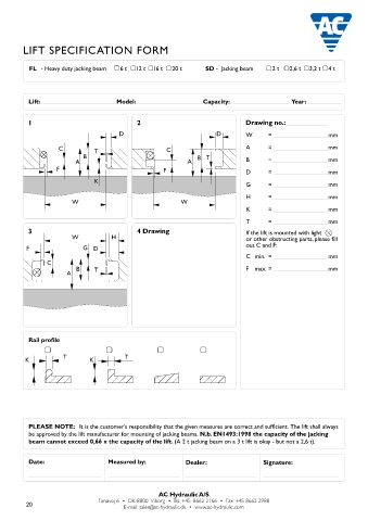
LIFT SPECIFICATION FORM                                                                                                 PIT SPECIFICATION FORM


           FL  - Heavy duty jacking beam   6 t   12 t  16 t   20 t   SD -  Jacking beam   2 t   2,6 t   3,2 t  4 t                GD    - Pit jack single ram   10 t   15 t   20 t   FL   - Heavy duty jacking beam   6 t   12 t   16 t   20 t
                                                                                                                                  GD    - Pit jack twin ram   10 t   15 t   20 t   SD  - Jacking beam           2 t   2,6 t  3,2 t   4 t
                                                                                                                                  GDT  - Telescopic pit jack   15 t              ABT - Support bridge           15 t
                                                                                                                                  GGD  - Floor pit jack    15 t                  AB  - Support bridge           20 t

          Lift:                        Model:                      Capacity:                   Year:
                                                                                                                                 1                                  2             W           T         Drawing no.:
                                                                                                                                                W             T
          1                                  2                                   Drawing no.:                                                                       E                                   Please measure various places along
                                                                                                                                E       D                                                               the length of the pit. Max 12 mm
                                        D                              D         W      =                  mm                                        B                      C                           variation between W min and W
                                                                                                                                                                                                        max. throughout the pit length
                    C           T                      C                         A      =                  mm                            C                                                              W min.  =                 mm
                            B                                    B T
                         A                                    A                  B      =                  mm                                     A                                  A                  W max.  =                 mm
                   F                                  F                          D      =                  mm                               F                                   F
                                                                                                                                                O                                 O                     A  min.  =                mm
                                K                                                                                                                                                  P
                                                                                 G      =                  mm                                   P                                                       B      =                  mm
                                                                                 H      =                  mm                                                                                           D      =                  mm
                        W                                   W
                                                                                 K      =                  mm                                                                                           E      =                  mm
                                                                                                                                 3             W           T        4 Drawing
                                                                                 T      =                  mm                                                                                           H      =                  mm
          3                                  4 Drawing                           If the lift is mounted with light               E
                        W            H                                           or other obstructing parts, please fill                                                                                T      =                  mm
                                                                                 out C and F:                                             D         B  H                                                If the pit is mounted with light
          F                 G  D                                                                                                                                                                        or other obstructing parts, please fill
                                                                                 C  min.  =                mm                             C                                                             out C and F:
                C
                          B     T                                                F   max.  =               mm                                    A                                                      C  min.  =                mm
                       A                                                                                                                     F
                                                                                                                                                O                                                       F   max.  =               mm
                                                                                                                                                P                                                       GGD150S - Floor pit jack
                                                                                                                                                                                                        O  min.  =                mm
                                                                                                                                                                                                        O  max.  =                mm

                                                                                                                                 Placing of saddle                  Option                              P   min.  =               mm

          Rail profile                                                                                                           The placing of top saddle excluding   Please note, mounting of different   P   max.  =           mm
                                                                                                                                 cross beam adaptor, safety stand and   options will increase the min. height:
                                                                                                                                 extentions is required:
                     T                   T                                                                                                                             Cross beam T4-1  = + 100 mm      Rolltype / Rail profile
         K                    K                                                                                                     above workshop floor     mm        Cross beam T5-1  = +   95 mm
                                                                                                                                                                       Cross beam T6-1  = +   55 mm
                                                                                                                                    levelling with workshop floor
                                                                                                                                                                       Cross beam T4-2  = + 145 mm
                                                                                                                                    below workshop floor     mm        Cross beam T5-2  = + 140 mm
                                                                                                                                                                       Cross beam T6-2  = +   90 mm
                                                                                                                                                                       Safety standS200  = +   65 mm
                                                                                                                                 The top of the cylinder will be positioned                                Conical/      Cylindrical/
                                                                                                                                 +/- 50 mm according to requested level    AS3         = + 100 mm          tilted        straight

          PLEASE NOTE:   It is the customer’s responsibility that the given measures are correct and sufficient. The lift shall always
          be approved by the lift manufacturer for mounting of jacking beams. N.b. EN1493:1998 the capacity of the jacking       PLEASE NOTE:  It is the customer’s responsibility that the given measures are correct and sufficient and
          beam cannot exceed 0,66 x the capacity of the lift. (A 2 t jacking beam on a 3 t lift is okay - but not a 2,6 t).                       that the pit is built and anchored to withstand the designated loading.


          Date:                     Measured by:              Dealer:                  Signature:                                Date:                     Measured by:              Dealer:                  Signature:


                                                    AC Hydraulic A/S                                                                                                       AC Hydraulic A/S
          20                     Fanøvej 6  •  DK-8800  Viborg  •  Tel. +45 8662 2166  •  Fax +45 8662 2988                                             Fanøvej 6  •  DK-8800  Viborg  •  Tel. +45 8662 2166  •  Fax +45 8662 2988
                                         E-mail: sales@ac-hydraulic.dk  •  www.ac-hydraulic.com
                                                                                                                                                                E-mail: sales@ac-hydraulic.dk  •  www.ac-hydraulic.com
   15   16   17   18   19   20   21   22   23   24   25