
Page 36 - Kraenzle_tillbehor_2021
P. 36
SAFETY DEVICES
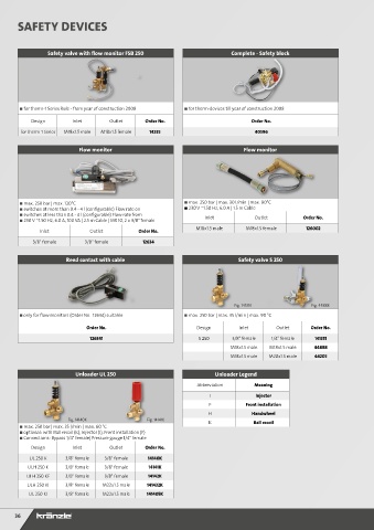
Safety valve with flow monitor FSB 250 Complete - Safety block
■ for therm-1 Series Rule - from year of construction 2008 ■ for therm-devices till year of construction 2008
Design Inlet Outlet Order No. Order No.
for therm-1 Series M18x1.5 male M18x1.5 female 14235 40596
Flow monitor Flow monitor
■ max. 250 bar | max. 120°C ■ max. 250 bar | max. 30 l/min | max. 90°C
■ switches at more than 0.4 - 4 l (configurable) Flow rate on ■ 230 V ~1.50 Hz, 6.0 A | 1.5 m Cable
■ switches at less than 0.4 - 4 l (configurable) Flow rate from
■ 230 V ~1.50 Hz, 6.0 A, 100 VA | 2.5 m Cable | MR 10, 2 x 3/8" female Inlet Outlet Order No.
M18x1.5 male M18x1.5 female 126002
Inlet Outlet Order No.
3/8" female 3/8" female 12634
Reed contact with cable Safety valve S 250
Fig. 141351 Fig. 44888
■ only for flow monitors (Order No. 12634) suitable ■ max. 250 bar | max. 35 l/min | max. 90 °C
Order No. Design Inlet Outlet Order No.
S 250
126341 S 250 3/8" female 1/4" female 141351
M18x1.5 male M18x1.5 male 44888
M18x1.5 male M20x1.5 male 44205
Unloader UL 250 Unloader Legend
Abbreviation Meaning
I Injector
F Front installation
H Handwheel
Fig. 14140K Fig. 14141K K Ball recoil
■ max. 250 bar | max. 35 l/min | max. 60 °C
■ optional: with Ball recoil (K), Injector (I), Front installation (F)
■ Connections: Bypass 1/4" female| Pressure gauge 1/4" female
Design Inlet Outlet Order No.
UL 250 K 3/8" female 3/8" female 14140K
ULH 250 K 3/8" female 3/8" female 14141K
ULH 250 KF 3/8" female 3/8" female 14142K
ULH 250 KI 3/8" female M22x1.5 male 141432K
UL 250 KI 3/8" female M22x1.5 male 141405K
36